


Centre of Excellence
NUCLEAR INTERACTIONS AND HADRONIC MATTER


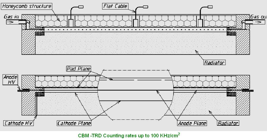
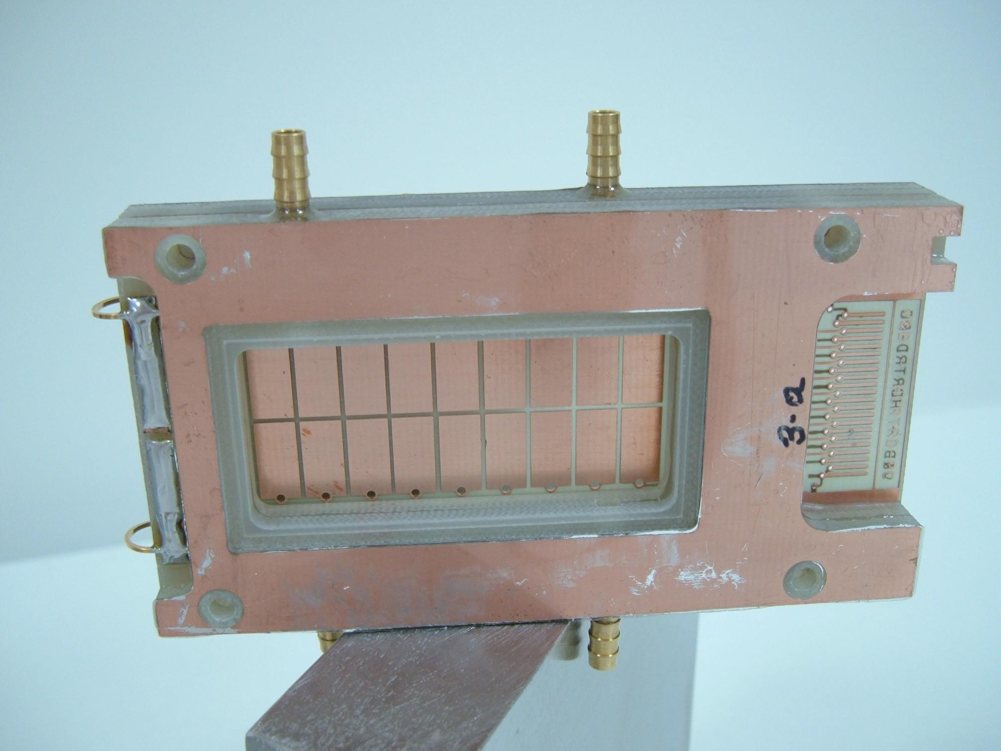
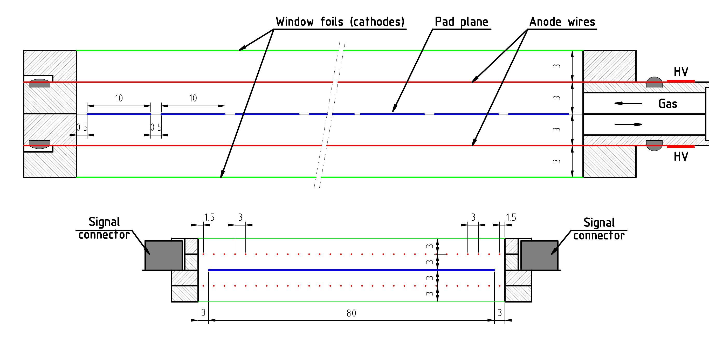
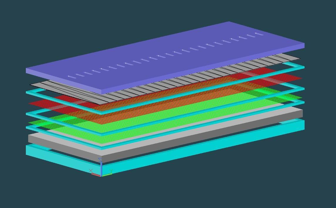
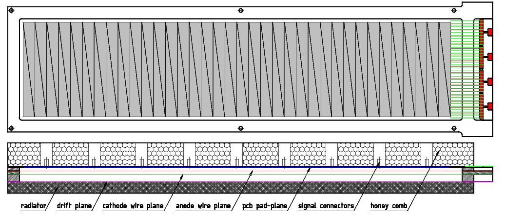
- type: radiator + MWPC;
- anode-cathode distance - 3mm;
- 2.5 mm anode pitch;
- maximum drift time ~ 100 ns;
- channel size ~ 6 cm2.
- anode-cathode distance - 3mm;
- 2.5 mm anode pitch;
- maximum drift time ~ 100 ns;
- channel size ~ 6 cm2.
Goal of the experiment: detector performance in high counting rate environment
| ■ | The signal doesn't decrease significantly up to 100 kHz/cm2; the configuration with split anode seems to have a better behaviour; |
| ■ | The position resolution at low rate is ~350 µm; the observed degradation for higher rate is smaller than 50 µm; |

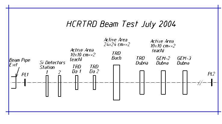
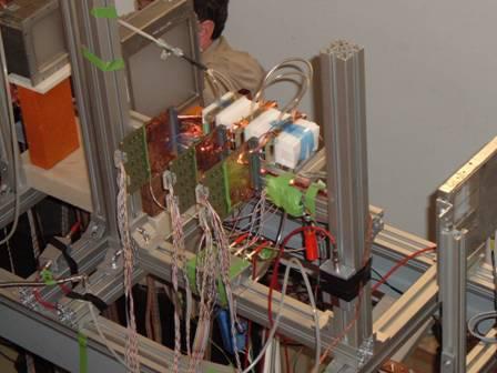
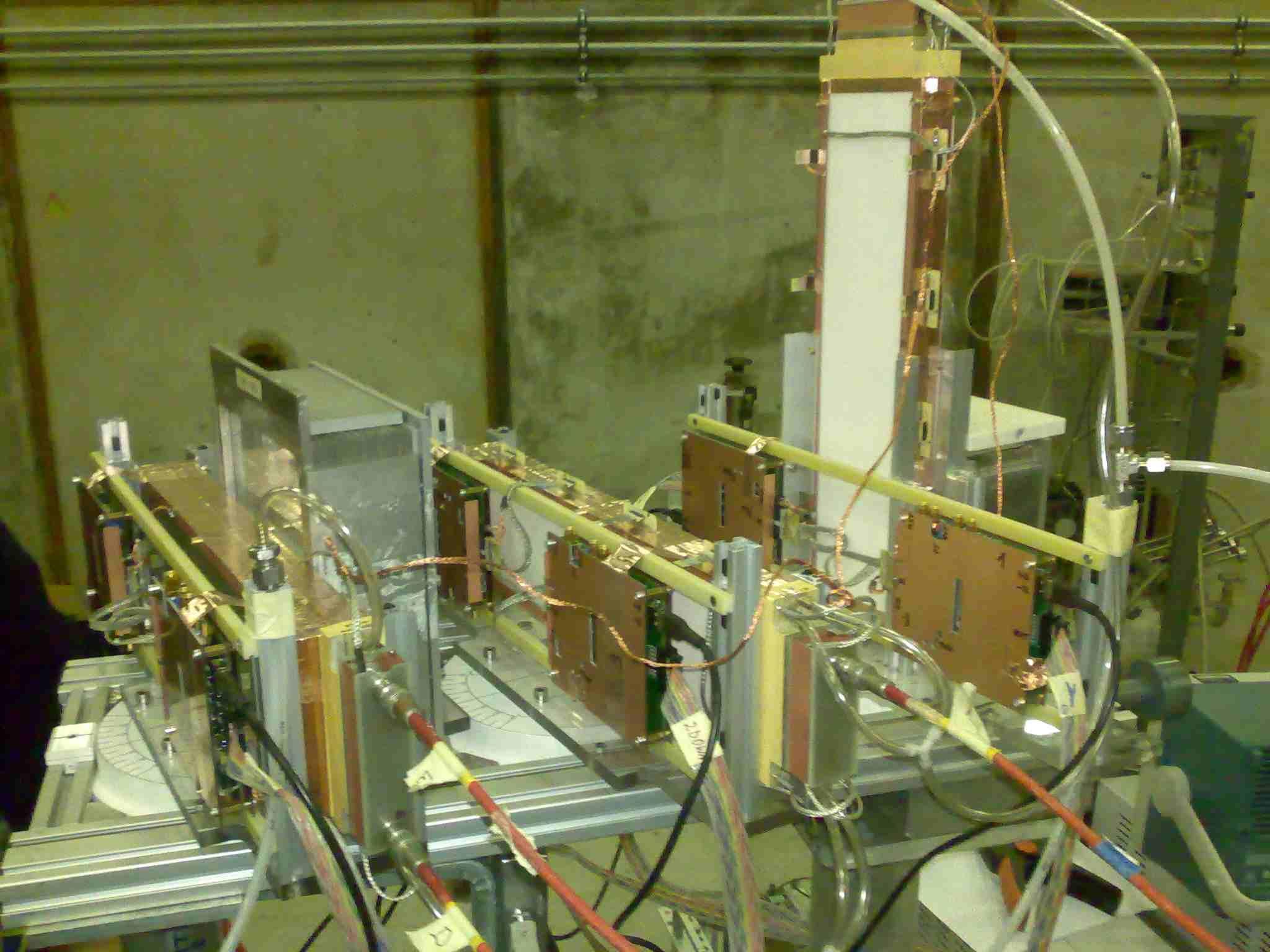
The first prototype HCRTRD were tested in-beam in July 2004 @ GSI Darmstadt

Goal: to increase the conversion efficiency of the TR in one layer conserving the rate performance and the number of the readout channels of the first prototype .
Solution: mirrored MWPC relative to a common double sided pad-plane electrode.

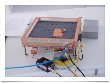
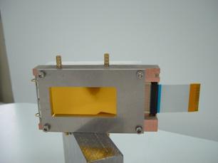
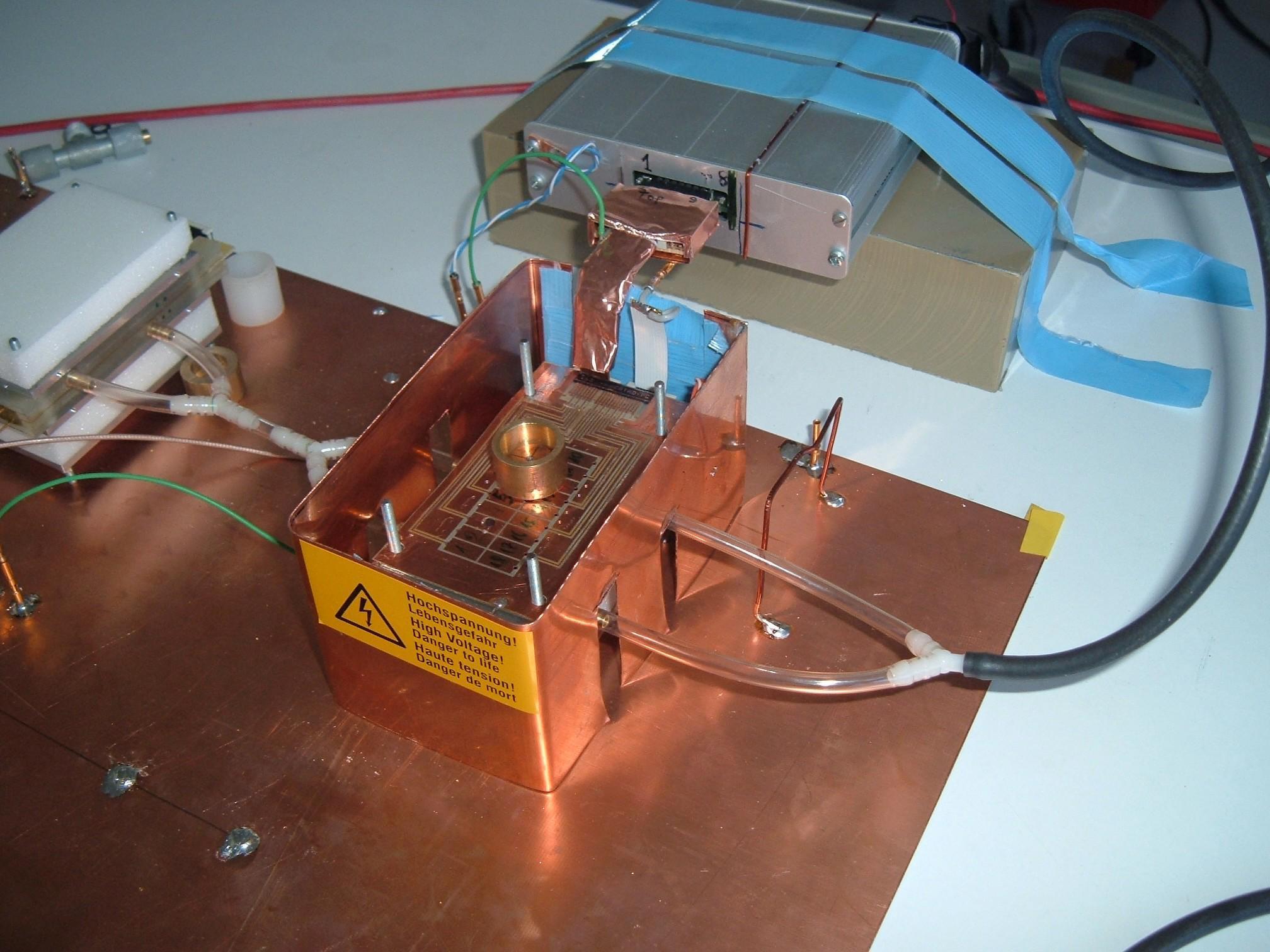
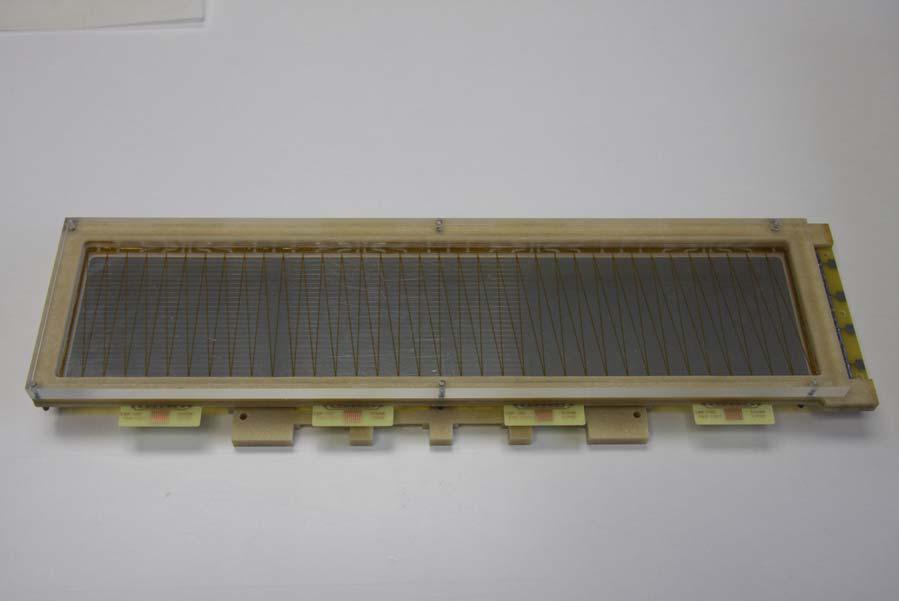
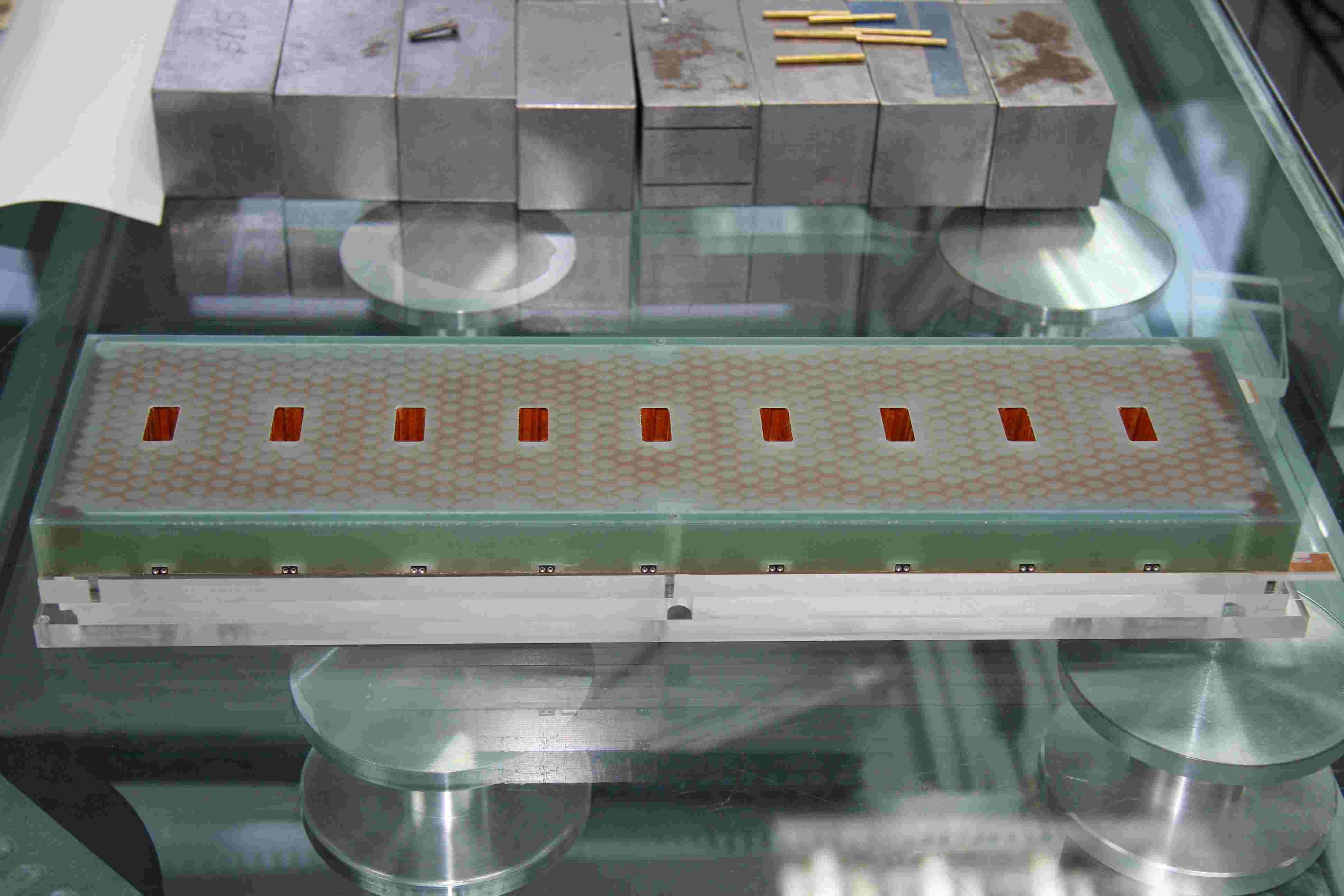
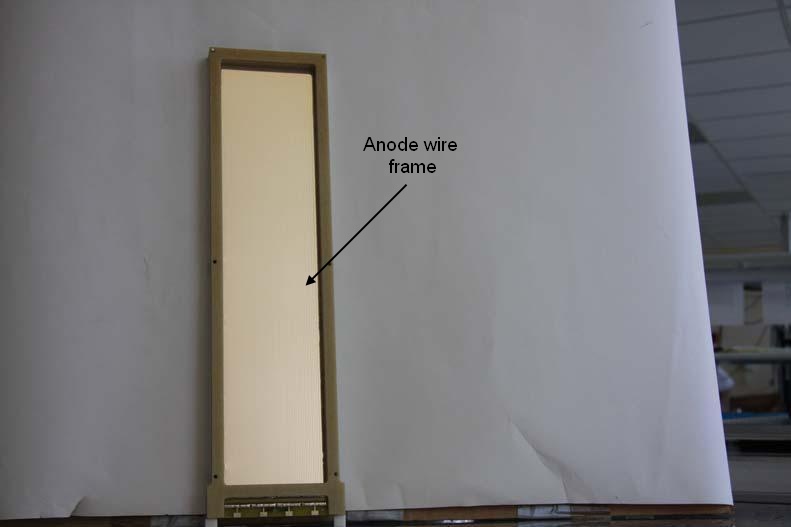
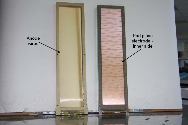
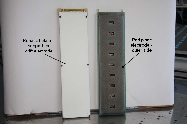
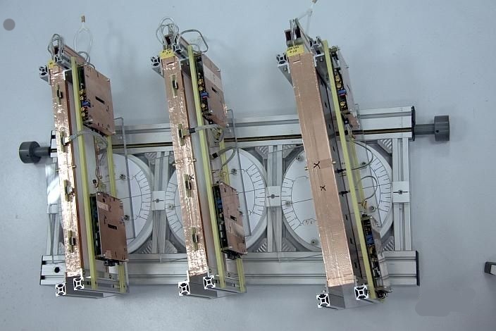
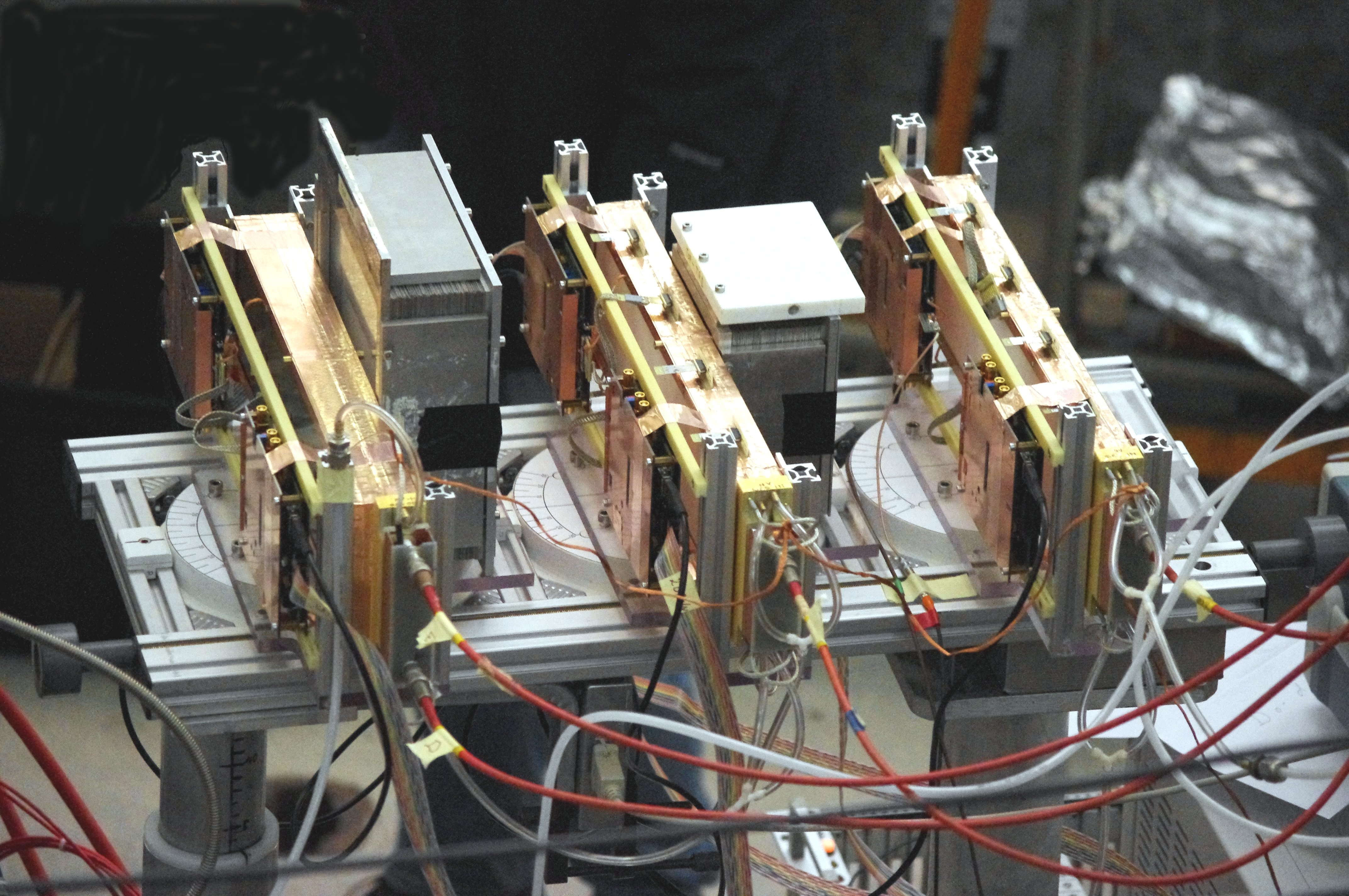
High Efficiency TRD for High Counting Rate Environment

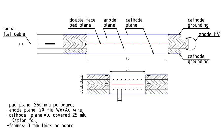


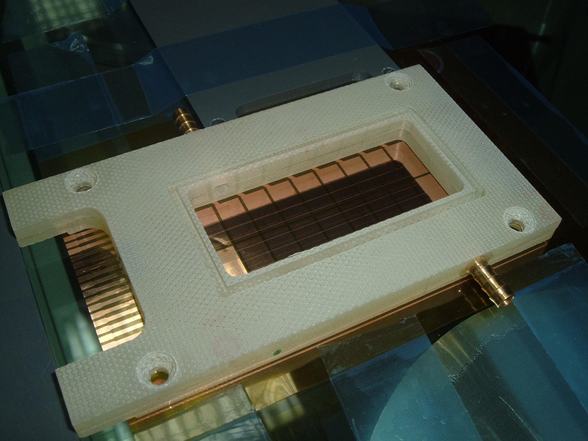
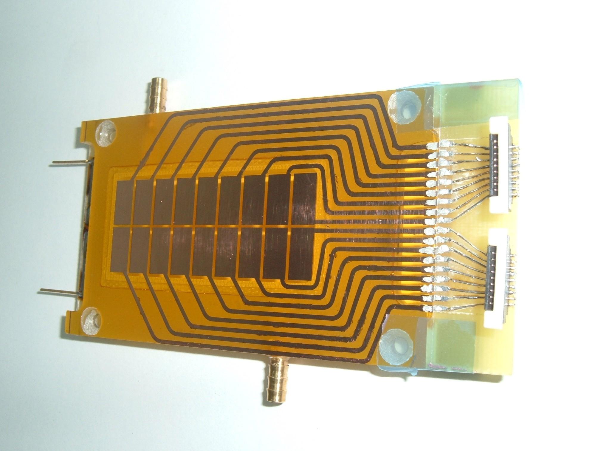
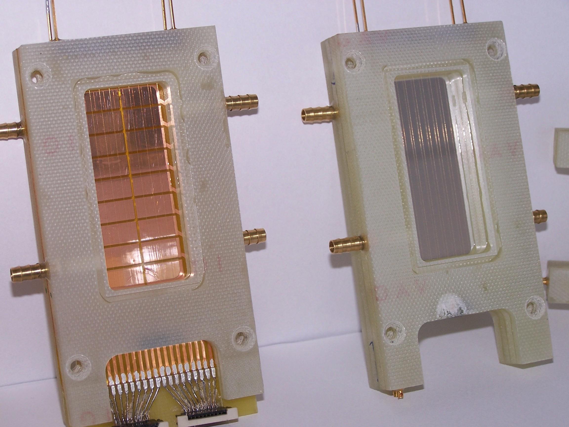
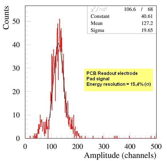
The first: the double -sided pad readout electrode has been madefrom PCB of 250 µm thickness.

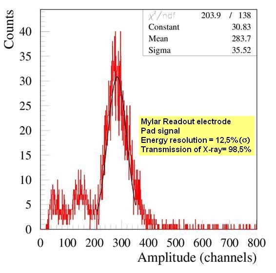
The second: the single -pad readout electrode made from mylar foil of 3 µm thickness, aluminized on both sides.
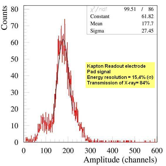
The third: the double -sided pad readout electrode made from kapton foil of 25 µm, covered with copper on both sides.

First results from in-Beam Tests @ SIS, GSI-Darmstadt

IFIN-HH


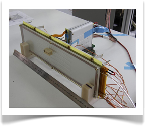
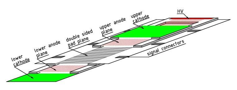
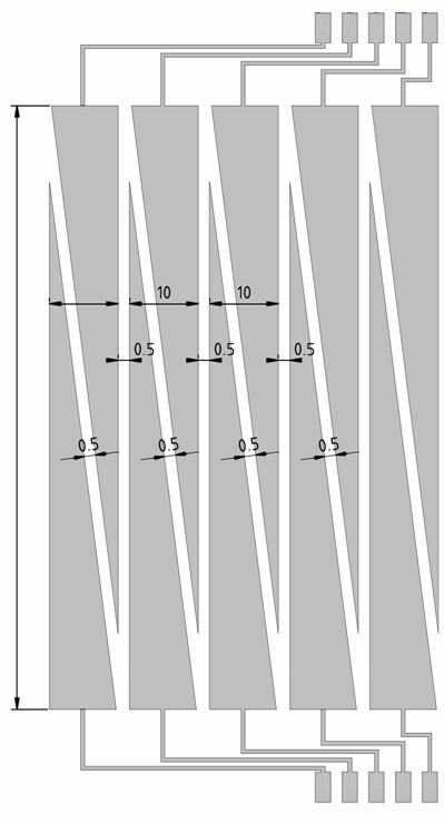
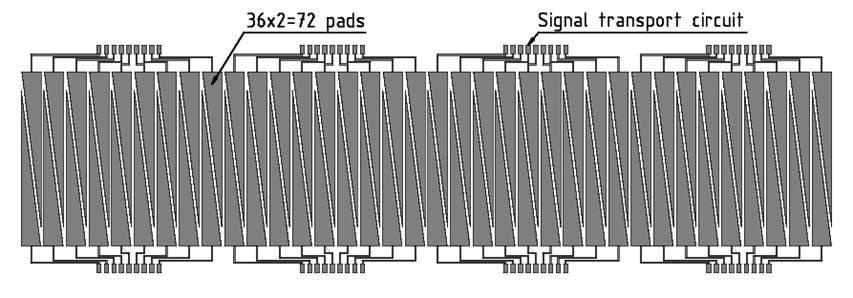
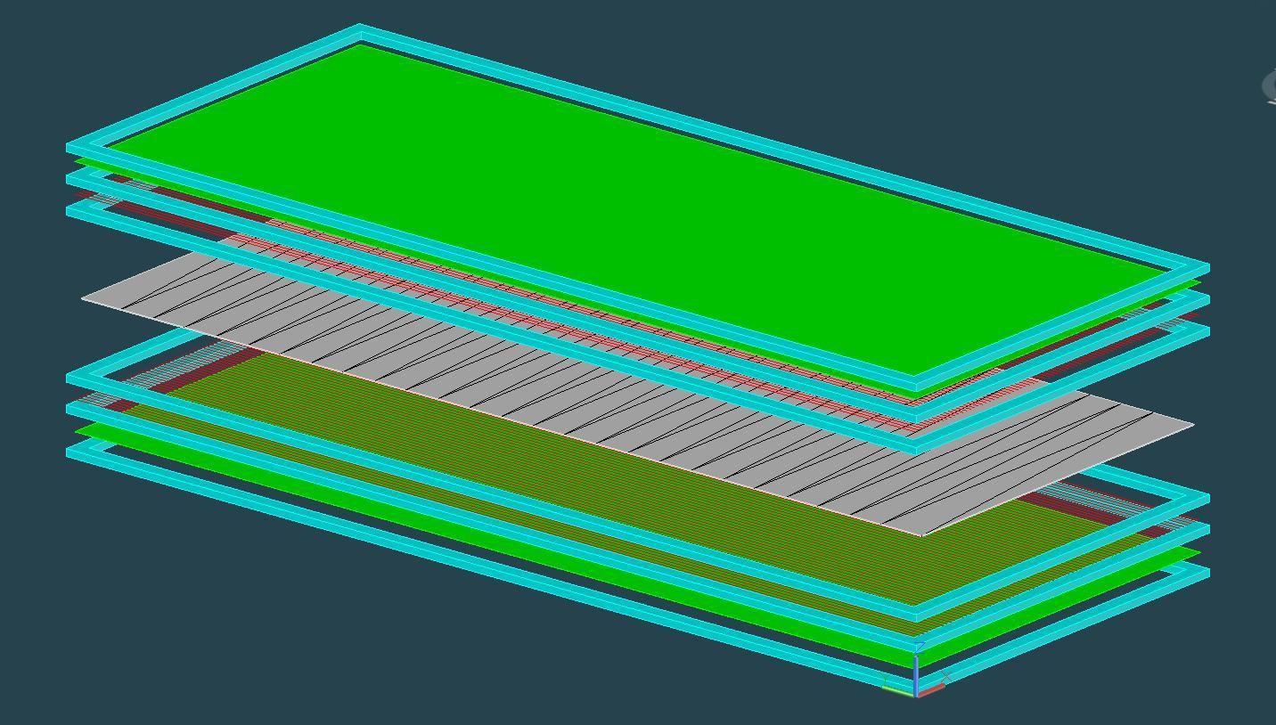
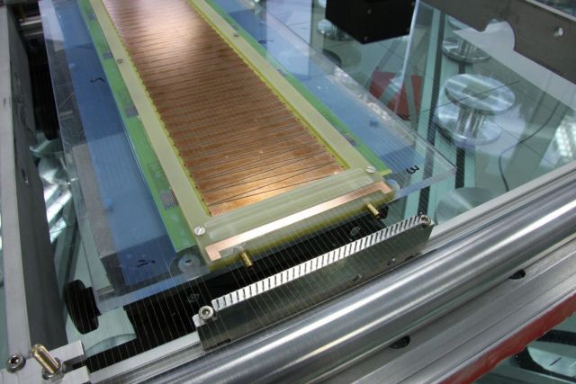
The prototype consists of two individual multiwire proportional chambers (MWPC) that share a thin common central readout electrode. The rectangular pads of the previous prototypes were split on diagonal for position determination in both coordinates: across and along the pads, respectively. Measurements with X-ray sources showed a very good energy and position resolutions. These results open the possibility of constructing large TRD arrays for high counting rate experiments with a reasonable number of layers and very good two-dimension position information.
Geometry


First prototype version


Second prototype version
- 3 mm anode-cathode distance
- 3 mm anode wire pitch
- 3 mm anode wire pitch
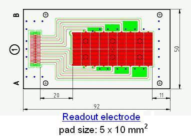
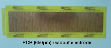
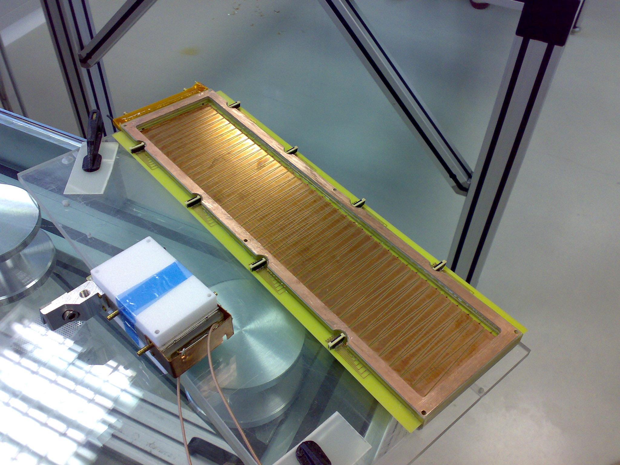
Readout electrode
PCB, 300 µm thickness
PCB, 300 µm thickness


- 3(4) mm anode-cathode distance
- 3 mm anode wire pitch
- 3 mm anode wire pitch
Readout electrode
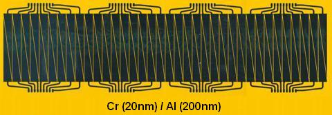
Cr(20 nm)/Al(200nm) on 25 µm kapton foil
Cr(20 nm)/Al(200nm) on 25 µm kapton foil


Read-out electrode -
pad geometry
pad geometry
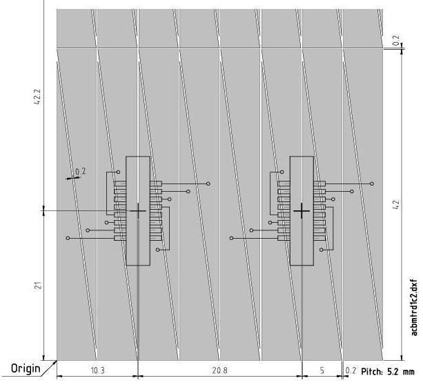
Single-sided split pad TRD


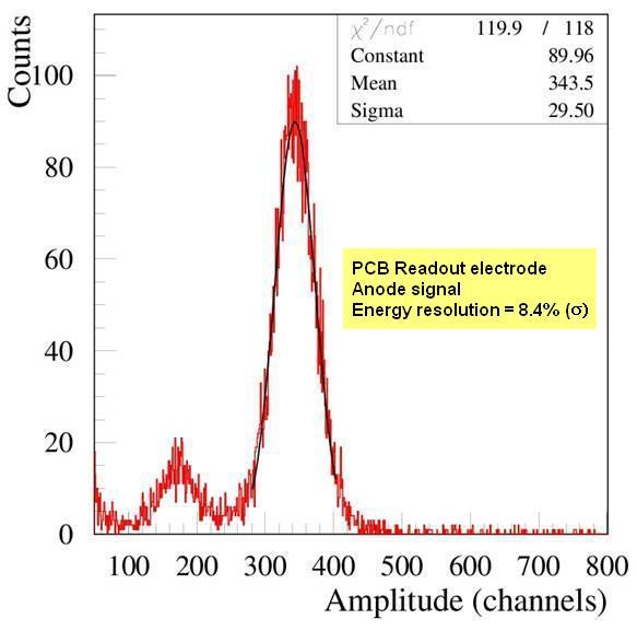
The obtained energy resolution @ 55Fe source for each of them was very good.
The position reconstruction in both x and y direction using 238Pu X-ray source was demonstrated.
The position reconstruction in both x and y direction using 238Pu X-ray source was demonstrated.

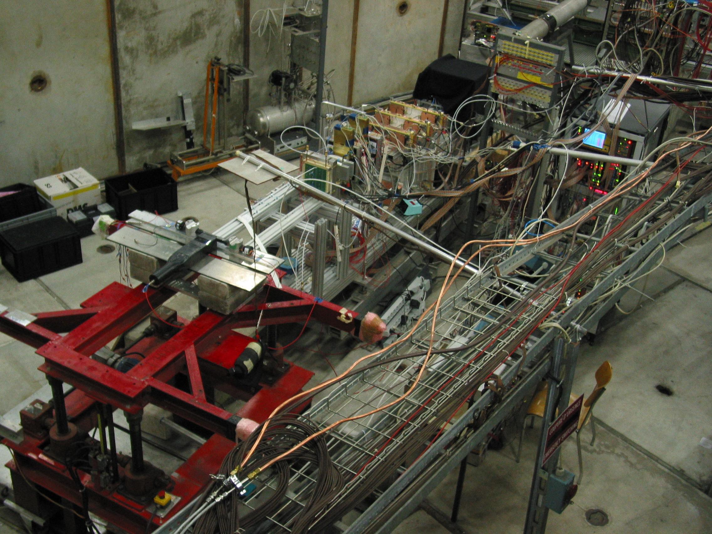
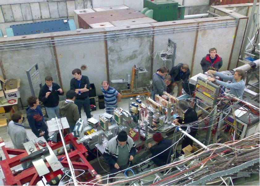

} first in-beam combined test
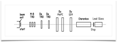
The in-beam test :
- excellent in-beam test conditions @ PS-CERN
- very good coordination of the in-beam test
- preliminary results show an excellent e/p discrimination « based on both:
- detector architecture
- FASP - FEE
- excellent in-beam test conditions @ PS-CERN
- very good coordination of the in-beam test
- preliminary results show an excellent e/p discrimination « based on both:
- detector architecture
- FASP - FEE

| ■ | 2 Scintillatorarrays (ToF, trigger): each array - 4 scintillatorpaddles (4 x 1 x 0.5 cm3each) |
| ■ | 2 Si -Strip Detectors (beam profile) |
| ■ | Cherenkov detector + Pb-glass calorimeterFADC readout ; DAQ (MBS) |
| ■ | Readout electrode: PCB, 300 µm thickness |
| ■ | 4 mm anode-cathode distance |
| ■ | 4 mm drift distance |
| ■ | 3 mm anode wire pitch |
| ■ | 1.5 mm cathode wire pitch |
